Showing posts with label Computer Hardware Troubleshooter. Show all posts

January 25, 2010

Steps to Fix Printer Spooler SubSystem App Error.


You may experience any of the following symptoms on your Windows XP-based computer.Generally you can see Printer Spooler Subsystem Error while accessing the printer and Fax Folder,sometime during printing,sometime when you try to start the Print Spooler service.
The Error message is like this

Spooler subsystem app has encountered a problem and needs to close.

This issue may occur if a third-party printer driver or a third-party service that is installed prevents you from adding printers, or if the third-party printer driver or the third-party service affects the functionality of a newly installed printer.

December 24, 2009

How to Check for Dead Pixels on LCD Monitors


If you have an LCD monitor for your PC, then sometimes some pixels on the LCD might not work properly. A defective (hot, dead or stuck) pixel is a pixel that does not illuminate properly or does not display the correct color output. It usually looks like an annoying black, white or colored spot on your screen. It is not easy to find dead pixels directly on your monitor. InjuredPixels is a freeware tool which llows you to easily check for dead or defective pixels on LCD monitors


It can be used to test new LCDs before purchasing or during the warranty period. InjuredPixels is very easy to use and can be run directly from the Internet without installation. When you execute the program, it actually fills the entire screen with a primary or custom color, allowing you to inspect the screen for pixels that do not match the selected color.It is User Friendly Software


InjuredPixels runs on Windows 7, Windows Vista and Windows XP with Microsoft .NET Framework 2.0 or above. The main executable program file of InjuredPixels natively runs on both 64-bit and 32-bit versions of Windows.


December 9, 2009

Portable Hard Drive Quick Defragmenter Tools For USB Drive


Here is the Portable defrag tools list that suitable stored on USB drive for hard drive defragmenter purpose. Defragment utility has been become important tools for windows user to make sure the files fragmentation is well organized and recover or repair the hard disk bad cluster.

However, the default defragment tools on Windows operating system is eventually slow and less functionality. So, below show a list of free Portable hard drive defragmenter tools can been use to defrag your hard disk for better performance and recover bad cluster. Meanwhile, this portable defrag tool doesn’t requires software installation, which you can run it directly from USB drive or removable storage drive.

Best Free Portable Hard Drive Defragmenter Tool:

WinContig - Portable Defragment Tool


Portable Defragment tool do not requires any installation directories or registry entries install on your computer. It can help windows user performs quickly defrag files and folders without having to defrag the whole disk for better optimization and performance.


PageDefrag - Portable Defrag Tools


PageDefrag uses advanced techniques to provide you what commercial defragmenters cannot: the ability for you to see how fragmented your paging files and Registry hives are, and to defragment them. In addition, it defragments event log files and Windows 2000/XP hibernation files (where system memory is saved when you hibernate a laptop).

MyDefrag ( Previously known as JKDefrag)


This defragmenter tools comes with better defrag features and GUI interface compare to JKDefrag. Meanwhile, it also integrated with Microsoft defragmentation api as the core defragmenter engine which it will load fast, low overhead, with better optimization on your hard disk perfor
mance.

Auslogics Disk Defrag - Portable Disk Defragment Tool

Auslogics Disk Defrag is a compact defragmentation tool that supports FAT 16/32, and NTFS (with compressed and encrypted files). It helps in maintaining high-level disk performance and speeding up your PC. Plus more, Auslogics Disk Defrag can also defrag removable storage media and ‘View detailed reports’ of Defragmentation Results.

With above portable hard drive defragment tools, you can easily defrag hard drive without installing defrag software on computer. If you know portable defrag tools should includes on the list, let us know via comment.


December 5, 2009

Steps to install PCI VGA(AGP) Card to Computer Mother board

One of the easiest installs on your computer is to install PCI cards. There are about a million different types of PCI cards.

To install PCI cards, you need to:

  • Unplug your computer from the wall and remove your computer's case cover so that you have plenty of room to work. More on this here. Also have your antistatic wristband on because PCI cards are VERY sensitive to static electricity.

  • Locate your PCI card slots (labeled A) on your motherboard. Then use a screwdriver to remove the screw (labeled B) holding the PCI slot cover. Once removed, set aside the screw, you'll need that later!
  • Align your PCI card with the slots on the motherboard and make sure the hole in the face of the PCI card lines up over the hole which you removed the screw.
  • Now to install the PCI slot card, firmly press down on it until it is in position. Finally, replace the screw that you removed before to secure the PCI card into place.
  • Troubleshooting a PCI card install


  • Plug your computer back in and turn it on. Your computer should detect the new card and be prepared to install any new drivers.

  • Here are a couple tips if you have trouble when you install your PCI card.

    • If your computer doesn't turn on make sure the power cable is plugged into the wall and plugged into the computer's power supply.
    • After installing your PCI card, if your computer turns on but beeps a couple times and the operating system does not load, repeat the install process but try the PCI card in different slots on the motherboard, it is possible that you have a bad slot.
    • If all else fails when you install your PCI card, contact its manufacturer for more help.

    December 2, 2009

    How Monitor Fan Speeds Temperatures and Voltages in PC


    Speed Fan monitors
    controls
    fan speeds, temperatures and voltages in computers with hardware monitor chips. Speed Fan can even access S.M.A.R.T. info for those hard disks that support this feature and show hard disk temperatures too, if supported. Speed Fan can even change the FSB on some hardware. At the lowest level, Speed Fan is a hardware monitor software, but its main feature is that Speed Fan can control fan speeds according to the temperatures inside your pc, thus reducing noise and power consumption.


    Download Free SpeedFan 4.34

    November 11, 2009

    How to Replace CMOS Battery

    Introduction and Lithium Battery


    Every PC motherboard has a battery. That battery serves two purposes: to feed the configuration memory (also called CMOS) and to feed the real time clock of the computer (the one that show the date and the time).

    An indication it is time to change the motherboard battery is receiving one of the following error messages when you turn on your computer: CMOS CHECKSUM FAILURE, CMOS BATTERY STATE LOW, CMOS SYSTEM OPTIONS NOT SET and CMOS TIME AND DATE NOT SET. Another indicator of a low battery is a clock that, after being set, runs well while the computer is on, but shows the wrong time when the computer is turned on the following day (it is late).

    The motherboard battery can be built using three different technologies: Nickel-cadmium (NiCd), NVRAM (Non-Volatile RAM) and Lithium (Li). The Lithium battery, which is a round one (the size of a coin) and can be easily found at watchmaker's and computer parts stores, has long been the most used type. To buy one of these batteries, all you have to do is to look for a model CR2032 one.

    Replacing the motherboard lithium battery demands some care. It seems to be a simple task, but it is not.

    The lithium battery may use basically three socket types: socket with upper tab (Figure 1), socket with lateral tab (Figure 2), and the socket into which the battery stands instead of lying (Figure 3).

    Lithium Battery

    Figure 1: Socket with upper tab.

    Lithium Battery

    Figure 2: Socket with lateral tab.

    Lithium Battery

    Figure 3: Another kind of battery socket.

    While the replacement of the battery in the socket with the lateral tab or of the one that stands is simple (Figures 2 and 3) – all you have to do is draw back the tab using your finger or a small screwdriver and replace it – the replacement of the batter that has an upper tab covering it (Figure 1) demands extra care. In this type of socket, if you raise the metallic tab to replace the battery, it will lose its pressure and will not make contact with the battery anymore, damaging the socket. In this case, the correct replacement of the battery in done pressing a small plastic lock at the side of the socket with the fingers or using a small screwdriver. That will allow the battery "to slide" laterally, not damaging the upper tab.

    Whatever the socket used, don't forget that the replacement of the battery should be done while the computer is off

    Related Articles

    How to Replace CMOS Battery

    How to Repair Monitor

    How to Change Mother Boards in Desktop?

    How to Upgrade a Computer's BIOS

    How to Repair SMPS

    Intel Atom Processor

    Mother Board Basics

    How to Repair Monitor

    Computers are useless without a monitor. You can't surf the Net or see what you typed on the keyboard. It's a good thing that computer monitors are virtually trouble free. Besides checking to see if it's plugged in and making a few adjustments there's little you can do to fix it without specialized help. Even so, let's take a look at how they work and how to tackle something you can fix, the monitor fuse.

    How Does It Work?

    Computer Monitor Repair, Copyright Fix It Club: Common Repairs Made Easy!

    Components of a typical computer monitor.

    A computer monitor, sister to the television monitor, displays information from a computer on a screen. The monitor uses digital values sent by a computer processor to create a stream of electrons that light up phosphors on the inside of the screen. The signals are in each of the three primary colors, combined into various color signals that seem to move across the screen. Portable computers use a screen made up of liquid crystal display (LCD) cells instead of phosphors. Computer monitors receive their signal from a monitor cable from the computer and their power from a separate electrical cord.

    What Can Go Wrong?

    Computer monitor problems are not always problems with the monitor. Testing of the monitor must be done with the computer . The monitor may not come on. The image on the screen may not be clear and bright

    How Can I Identify the Problem?

    If the monitor does not come on, make sure there is power to the electrical receptacle . Check the electrical cord . Check the connections between the monitor and the computer and make sure the computer is on. Test the line fuse (see below).

    Computer Monitor Repair, Copyright Fix It Club: Common Repairs Made Easy!

    Interior of a computer monitor. Identify but don't touch the power supply.

    If the image on the screen is not clear and bright, check your owner's manual for instructions on adjusting the monitor. Typically there are adjustment buttons on the monitor face below the screen.

    What Parts, Materials, and Tools Do I Need?

    Replacement cables and fuses are available from the manufacturer as well as from local computer shops. Tools you may need to access, test, and fix a computer monitor include these:

    • Screwdrivers
    • Multimeter

    What Are the Steps to Fixing It?

    Fix-It Tip

    A computer monitor gets its instructions from a video controller card in the computer. The card may be an add-on expansion card or it may be built into the main circuit board, called the motherboard. If it is a separate card, you may need to open the computer and make sure the card is firmly connected. Also check the flat data cable that runs between the video card and the motherboard, if so equipped.

    Computer Monitor Repair, Copyright Fix It Club: Common Repairs Made Easy!

    Locate, remove, and test the line fuse, typically located near the power cord entry.

    Test and replace a monitor fuse:

    1. Disconnect the monitor from the electrical receptacle and from the computer processor.

    2. Lay the monitor on a padded surface and remove the housing screws (some may be under pop-out tabs).

    3. Slide the rear housing off.

    4. Locate the line fuse typically near the power cord entrance. Remove the fuse from its holder and test it with a multimeter. Replace the fuse if it is faulty.

    Caution!

    For safety, follow the manufacturer's instructions in the owner's manual to discharge the video tube before working near it. In most cases this means using jumper wires to connect a 10,000-ohm resistor between the chassis ground or common ground and a screwdriver, and shorting the high-voltage lead by inserting the screwdriver under the suction cup.

    Troubleshooting Tips for New Monitors

    You are encouraged to make links to this article from your website and tell your friends

    Here are some basic trouble shooting tips for new monitors:

    1. The picture does not appear
      • Check to make sure the signal cable is firmly connected in the socket.
      • Check to see if the computer system's power is ON.
      • Check that the Brightness Control is at the appropriate position, not at the minimum.
    2. The Screen is not synchronized
      • Check to make sure the signal cable is firmly connected in the socket.
      • Check that the output level matches the input level of your computer.
      • Make sure the signal timing of the computer system is within the specification of the monitor.
    3. The position of the screen is not in the center
      • Adjust the H-Size, H-Phase or V-Size, V-Center controls.
      • Check if the signal timing of the computer system is within the specification of the monitor.
    4. The screen is too bright or too dark
      • Check if the Brightness or contrast control is at the appropriate position, not at the maximum or minimum.
      • Check if the specified voltage is applied
      • Check if the signal timing of the computer system is within the specification of the monitor.
      • Especially, check the horizontal frequency.
    5. The screen is shaking
      • Move all objects that emit a magnetic field, such as a motor or transformer, away from the monitor.
      • Check if the specified voltage is applied.
      • Check if the signal timing of the computer system is within the specification of the monitor.

    Related Articles

    How to Replace CMOS Battery

    How to Repair Monitor

    How to Change Mother Boards in Desktop?

    How to Upgrade a Computer's BIOS

    How to Repair SMPS

    Intel Atom Processor

    Mother Board Basics

    November 3, 2009

    How to Change Mother Boards in Desktop?


    Motherboards hold all the pieces that make up your computer. It supplies all the wiring and connections needed to make your computer run. However, you may feel that need to upgrade or replace your motherboard.
    Before anything can be done, you need to be absolutely sure that you have to upgrade your motherboard. As a stand-alone part, motherboards are probably the part that would least likely need an upgrade. Some reasons for having to upgrade would be:
    • Not enough space for an adequate amount of RAM
    • No slot for an adequate graphics card
    • Damage to the actual motherboard
    You then need to decide whether you want to keep the current parts of your computer, or buy completely new ones along with your motherboard.

    Keeping the Same Parts

    If you want to keep the same parts in you computer after purchasing a new motherboard, you need to start by looking at the parts you already have. In this way, you need to look for a motherboard that is compatible with your existing computer parts. This is essential because you do not want to buy a motherboard that is not compatible with any of the parts you already have.
    You may not know what parts your computer consists of. To find this out:
    • Right click on 'My Computer'
    • Go to Properties
    • Go under Hardware
    • Click Device Manager
    You can now see all the parts that your computer has. Remember to write these down for future reference.
    After doing this, you can start looking for a motherboard. Sites such as Newegg are a great way to compare and contrast different models.
    When looking for a motherboard, make sure that it has the following:
    • Enough RAM slots
    • A PCI slot that is compatible with your graphics card
    • A CPU Socket that is compatible with your CPU
    • Enough USB drives to comfortably fit everything you may want to plug in
    • Optional: Onboard sound to save some money and have a spare PCI slot
    Once you have chosen a motherboard, be sure to double check that all existing parts fit.

    Buying New Parts

    If you want to completely upgrade your PC and buy new components along with you motherboard, you are effectively building a new computer.
    All the parts that you choose must be based from your motherboard. Each part must be compatible with the motherboard you choose in order for your computer to run.
    When buying a brand new motherboard, look for:
    • Enough RAM slots
    • A PCI Express slot for a good graphics card
    • A widely accepted CPU slot to increase your CPU model options
    • Optional: Onboard sound
    Once you have purchased your motherboard, you are ready to install it.

    Taking out the Motherboard

    You will need just a screwdriver for the entire process
    1. First, disconnect all the wires behind your computer
    2. Start by taking out the largest wire that connects the power supply to the motherboard
    3. Move onto the smaller wires that are used for processes such as LED, Power Switch and Reset Button
    4. Take the larger ones out next: the wires running from the read/write drive and hard drive
    5. Open the case - you may need to use a screwdriver for this
    6. 'Ground' yourself by touching the large metal bar across the computer towards the top. Static electricity can completely destroy parts. Doing this gets rid of the static electricity in your body
    7. Start by taking off all the wires that are connected into the motherboard. You can move these wires to the side.
    8. The graphics card is located towards the bottom of the motherboard. There will most likely be a switch or latch where the graphics card extends to the back of the computer. Lift or switch this latch.
    9. Very gently, begin by pulling up the end of the graphics card is closest to the back of the computer. This side should lift up.
    10. There is a hook on the other end of the graphics card. Be aware of this when fully detaching the card. Lay the card to the side when you are done.
    11. You now have to take off the heat sink and fan located on the CPU.
    12. Detach the wire from the heat sink and fan from the motherboard.
    13. Depending on what model of CPU you have, you need to take off the heat sink and fan first. There should be a latch that you lift that will release both the heat sink and fan.
    14. You now need to take out the actual motherboard.
    15. There will be screw all around your motherboard. Unscrew these and you should be able to lift it up out of the computer relatively easy.
    16. Once you have the motherboard out, you need to take off the RAM and actual CPU.
    17. Lift the metal latch located above the CPU socket.
    18. Gently lift the CPU up and off the motherboard. You may need to move it from side to side a little to loosen it.
    19. On either side of the RAM will be some handles. Push these down and the RAM card should pop right out. Be careful to not use too much force.
    Remember:
    • No water or food anywhere near where you are working
    • Never use force if something is not going right

    Re-Attaching the New Motherboard

    Once you have successfully taken out your old motherboard, you can now proceed to install the new one. The steps taken here are basically the same as detaching the motherboard, but in the opposite way.
    1. First, put the CPU onto the motherboard and close the metal latch.
    2. Open the handles on the RAM slots and push the RAM into it. There are corresponding holes on the RAM cards so make sure these are aligned.
    3. You should here a click with the RAM is attached properly.
    4. Take the motherboard and place it in the computer.
    5. Depending on the two types of motherboard you have, you may need to realign the 'legs' that the motherboard is screwed onto. In this case, take out the legs and screw them back in the corresponding shape to the larger holes on the motherboard.
    6. After doing this, screw in the motherboard.
    7. Plug the power supply into the motherboard.
    8. As before, you now need to replace the heat sink and fan on the motherboard. Place them onto the CPU and latch it in.
    9. Remember to plug the wire leading out of the fan into the motherboard for power.
    10. You now need to install your graphics card.
    11. Sliding in the end of the graphics card that has the hook first, slowly lower the other end until it fits nicely onto the motherboard. You may need to lift or switch a handle to secure it in place.
    12. You now have to reattach all the wires you took out.
    13. Start with the larger ones. Since you should not have removed the read/write drive and hard drive when taking out your motherboard, they should still be in place. Plug these into the respective slots.
    14. Now plug the rest of the wires in.
    Remember:
    In doubt, always refer to the motherboard manual.Testing the new Motherboard
    After installing your new motherboard, you are ready to test it out. Reconnect all the wires you had into their respective slots on the back panel.
    Turn the computer on. If you hear a beep, that is the sound of the motherboard detecting the hard drive. This is perfectly normal.
    Changing your motherboard should not result in any major changes to the software on your computer. Make sure that everything still runs smoothly

    Related Articles

    October 27, 2009

    How to Upgrade a Computer's BIOS

    Step 1

    Check your computer or motherboard manual for any information about upgrading the BIOS.

    Step 2

    Reboot your computer and enter the Setup screen. Check your computer or motherboard manual for information on how to do this.

    Step 3

    Press the Print Screen key to make a record of each page of your settings.

    Step 4

    Find out the manufacturer and model of your current BIOS. Check for the information as your computer boots, or find it in the Setup screen information you printed. If neither method works, check the BIOS chip for identifying information.

    Step 5

    Check the manufacturer's Web site to see if the BIOS can be "flash" upgraded. If so, download the utility program. If not, proceed to Step 6

    Step 6

    Copy the program to a floppy disk.

    Step 7

    Follow the manufacturer's instructions for running the program. Skip to Step 10.

    Step 8

    Contact the manufacturer of your BIOS chip to find out if an updated chip is available, and if that chip will fit into the same slot on your motherboard.

    Step 9

    Get and install a new BIOS chip, if available. Search the Internet for installation instructions.

    Step 10

    Reboot your computer and enter the Setup screen. Change the Setup back to the previous settings if necessary or desired.

    Tips & Warnings
    • Your motherboard may need to be replaced in order to upgrade the BIOS. If so, consider buying a new computer instead.
    • If you use flash BIOS software that wasn't specifically made for your BIOS model, the computer probably won't boot.
    • If you install the BIOS incorrectly, the computer probably won't boot. If you do not understand the instructions or lack good manual dexterity, have a qualified technician install the BIOS for you.

    Related Articles
    How to Replace CMOS Battery

    How to Repair Monitor

    How to Change Mother Boards in Desktop?

    How to Upgrade a Computer's BIOS

    How to Repair SMPS

    Intel Atom Processor

    Mother Board Basics

    June 17, 2009

    Secrets Of SMPS Repair And Troubleshooting (Switch Mode Power Supply)

    SMPS repair sometimes can be easy and sometimes are quite difficult to solve the problem. The power supply fault could be an open start up resistor only or could be even more than ten components burnt due to heavy lightning strike. In this article, I’m going to explain to you the power supply problems that caused by defective components at secondary side. Sometimes no power, power blink and low output power symptoms are due to problems in the main circuit board. It is not necessary the fault must be in the primary power section and shorted secondary output diodes.

    The fault can be further down the secondary output lines which are in the main board. If you had measured all the components in the power supply section and could not find the defective component, then try troubleshoot components beyond the power supply section. A shorted small ceramic capacitor in the main board can cause the whole power supply to malfunction.

    True case study- A Samtron Monitor 4Bn sent for repair with the complaint of no power. After troubleshooting the smps section for sometime, I’ve concluded that the power supply is working and suspect something shorted after the secondary output diodes and this made me to trace beyond the power supply unit. By using the explanation above, I managed to traced and found a shorted small resin ceramic capacitor located at the 80 volt line in the Monitor color board. The capacitor shorted to ground and made the power supply to stop operating.

    The value of the shorted capacitor was .22 microfarad 100 volt. Replacing only the small capacitor brought the power supply back to life again. In smps repair, we as an
    electronic
    repairer must know how to distinguish as which section is giving problem. Spending and concentrating your whole time to check on a working section is just a waste of time, you should only concentrate on section that have problems so that you could locate the fault and make the equipment work again.


    Related Articles

    How to Replace CMOS Battery

    How to Repair Monitor

    How to Change Mother Boards in Desktop?

    How to Upgrade a Computer's BIOS

    How to Repair SMPS

    Intel Atom Processor

    Mother Board Basics

    June 12, 2009

    Intel Atom Processor

    Intel Atom Processor


    Produced : 2008–present
    Common manufacturer(s ) : Intel
    Max. CPU clock : 800 MHz to 2 GHz
    FSB speeds : Data transfers at 400 MHz to 667 MHz
    Min. feature size : 45nm
    Instruction set : x86, x86-64 (not for the N and Z series)
    Cores : 1, 2
    Package(s) : 441-ball µFCBGA
    Core name(s) : SilverthorneDiamondville

    Intel Atom is the brand name for a line of x86 and x86-64 CPUs (or microprocessors) from Intel, designed in 45 nm CMOS and used mainly in Notebooks. Silverthorne is called the Atom Z series and Diamondville is called the Atom N series. As of June 2009, the most used chips in the Netbook retail market are Z520, Z530, and N270

    Prior to the Silverthorne announcement, outside sources had speculated that Atom would compete with AMD's Geode system-on-a-chip processors, used by the One Laptop per Child project, and other cost- and power-sensitive applications for x86 processors. However, Intel revealed on October 15, 2007 that it was developing another new mobile processor, codenamed Diamondville, for OLPC-type devices.

    "Atom" was the name under which Silverthorne would be sold, while the supporting chipset formerly code-named Menlow was called Centrino Atom. Intel's initial Atom press release only briefly discussed "Diamondville" and implied that it too would be named "Atom", strengthening speculation that Diamondville is simply a lower-cost, higher-yielding version of Silverthorne with slightly higher TDPs at slightly lower clock speeds.

    At Spring Intel Developer Forum (IDF) 2008 in Shanghai, Intel officially announced that Silverthorne and Diamondville are based on the same microarchitecture. Silverthorne will be called the Atom Z series and Diamondville will be called the Atom N series. The more expensive lower-power Silverthorne parts will be used in Intel Mobile Internet Devices (MIDs) whereas Diamondville will be used in low-cost desktop and notebooks. Several Mini-ITX motherboard samples have also been revealed.Intel and Lenovo also jointly announced an Atom powered MID called the IdeaPad U8. The IdeaPad U8 weighs 280 g and has a 4.8 in (12 cm) touchscreen providing better portability than a netbook PC and easier Internet viewing than a mobile phone or PDA.
    Atom N series
    On March 2, 2008, Intel announced a low-cost mobile processor (code-named Diamondville) to be used in the Classmate PC Netbook. It is used in Intel's low-cost Mini-ITX motherboards (code-named "Little Falls") and in a number of netbooks.It will supersede Conroe L as the N270 (2.5 W TDP) for netbooks and as 230 (4 W TDP) for nettops, each running at 1.6 GHz per core with a 533 MHz FSB speed. An N280 with a 1.66 GHz clockspeed and a 667 MHz FSB has since appeared.
    Atom 300 series
    On September 22, 2008, Intel announced a new dual-core processor (unofficially code-named Dual Diamondville) branded Atom 330 of the Atom 300 series to be used in desktop computers. It runs at 1.6 GHz and has a 8 W TDP rating. Its dual core comprises two Diamondville dies next to each other on a single package (substrate).
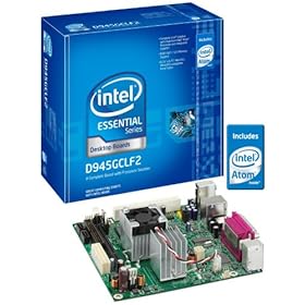
    The intel D945GCLF2 is a mini-ITX board that contains the Atom 330.
    The Zotac IONITX-A-U is a board that pairs the Atom 330 with NVIDIA's GeForce 9400M chipset. The intel Atom CPU, when paired with NVIDIA's GeForce 9300M or 9400M chipset, is often called the NVIDIA ION platformRead More >>>>>>>>>>>>>>
    Advantages of Intel Atom Processor
    All Intel® Atom™ processors feature:
    1.Small Form Factor CPU Package
    2.Low TDP
    3.Power Optimized Front Side Bus
    4.Enhanced Data Prefetcher & Enhanced Register Access Manager


    Related Articles

    How to Replace CMOS Battery

    How to Repair Monitor

    How to Change Mother Boards in Desktop?

    How to Upgrade a Computer's BIOS

    How to Repair SMPS

    Intel Atom Processor

    Mother Board Basics

    May 30, 2009

    Mother Board Basics


    The Article
    A motherboard, also known as a main board, is the primary circuit board inside of a computer, and is where the central processing unit (CPU), memory, expansion slots, drives, and other peripheral devices are connected. The circuitry on a motherboard facilitates the communication between all of the devices in the computer, making them as critical to a system’s performance as items such as the CPU or memory.
    The core circuitry of a motherboard is referred to as its chipset, and generally the manufacturer of the motherboard is not the manufacturer of the chipset. Intel does produce motherboards with their own chipsets, but buying a motherboard brand such as Gigabyte, Biostar, and ASUS means getting a board with either a VIA, Nvidia, SIS, or Intel brand chipset.
    1. Form Factor
    The different basic shapes and sizes of motherboards are categorized as form factors. There are several standard form factors available, but some of the more common ones found in desktop computers include: (http://www.formfactors.org/developer/specs/atx2_2.pdf), ATX (http://www.formfactors.org/developer/specs/matxspe1.2.pdf), Micro ATX (mATX) (http://www.formfactors.org/developer/specs/FlexATXaddn1_0.pdf) FlexATX (http://www.via.com.tw/en/initiatives/spearhead/mini-itx/) and Mini-ITX
    The basic sizes of each are as follows:
    ATX: 12" x 9.6" (305mm x 244mm)
    Micro ATX: 9.6" x 9.6" (244mm x 244mm)
    FlexATX: 9.0" x 7.5" (229mm x 191mm)
    Mini ITX: 6.7" x 6.7" (170mm x 170mm)
    ATX and mATX are by far the most popular motherboard sizes for desktop computers, and as seen in the list above, are also some of the largest. More real estate on a motherboard allows for greater expansion possibilities and extra features, which make the use of these boards more flexible. A Mini-ITX board may feature just one slot for memory and one slot for an expansion card, while a typical ATX board may feature 4 memory slots and six slots for expansion cards.
    Each form factor has its own niche that it fits into, from workstations and gaming systems for larger boards to media centers and in-car computers for smaller boards. There is definitely overlap between the potential applications of each form factor, and other features and capabilities will also influence the targeted use.
    2. CPU Socket
    The major processor manufacturers, AMD and Intel, are constantly waging a battle to offer the fastest, most powerful processors available. Getting more speed and performance out of a relatively small chip generally requires a change to the physical dimensions as each new generation of processor is released. Therefore, motherboards need to evolve at the same pace in order to accept the new CPUs.
    Back in the day, AMD and Intel processors shared a common CPU socket, but those days were short lived. AMD and Intel have since been traveling down their own, relatively parallel, paths of performance and speed increases, while using different designs. Selecting a motherboard for a modern AMD processor eliminates the use of any Intel processor, and vice versa.
    AMD’s current offering for desktop processors includes the Athlon 64, which is available in Socket 939 and Socket 754 formats. The number in the names represents the number of pins present on the backside of the CPU that connect to the motherboard’s socket. The Socket 939 Athlon 64 therefore has a staggering array of nine hundred and thirty nine tiny pins to match up with the motherboard’s socket. The Chaintech VNF4 Ultra is an example of a Socket 939 motherboard based on Nvidia’s NForce4 Ultra chipset technology. In addition to these two sockets, many AMD processors, including Athlon XPs, Semprons, and Durons, share the Socket A format, also known as Socket 462 thanks to it having 462 pins for connecting to a motherboard.Socket adapters
    Intel’s latest offering for their Pentium 4 and Celeron processors, LGA 775, doesn’t have pins at all and basically swaps the pins to the motherboard for the socket. Perhaps this design move puts the burden of bent pin warranty claims on someone else, but it is fairly unique. The Biostar P4M80-M7 is an example of an LGA 775 motherboard based on the VIA P4M800 chipset. Other Intel processors still on the market utilize the Socket 478 format for Pentium 4 and Celeron processors.
    Although most motherboards support just one CPU socket, some applications benefit from having more than one processor to tackle the tasks at hand. Servers and high end workstations are two examples where a dual processor system, such as could be run on the Tyan Thunder i7500 motherboard, might make light work of more advanced applications.
    3. Components
    ‘Components’ is a fairly vague term to describe this section, but the items to be covered are fairly diverse. Computer systems all use memory, storage devices, and power supplies, but among the many differences motherboards have is the type and quantity of connections for these components.
    Most modern systems use DDR memory, but DDR-2 memory is becoming more common and will eventually become the standard. Although some boards provide slots for both types of memory, it is generally the case that either one or the other technology is supported. Besides operating differently, the physical difference of DDR having 184 pins and DDR-2 having 240 pins prevents them from being interchangeable. Going forward, users will have to decide whether they want to jump on the new technology bandwagon when selecting a motherboard, or to try to continue using their existing DDR for as long as possible. Regardless of technology, most motherboards come with 2 to 4 slots for memory, although as mentioned, Mini-ITX boards may just offer 1 slot.
    Hard drive technology is changing too, as mentioned in the Tech Tip comparing SATA to ATA hard drives. Most motherboards over the past few years have offered two ATA connections, which could support up to 4 drives. With SATA becoming more popular, some boards now offer a mix of ATA and SATA connections, while others have abandoned ATA all together, and instead offer multiple SATA connections which only support one drive each. In addition to type and quantity, motherboards can also offer choices in hard drive capabilities by integrating RAID controllers onboard, as found on the ASUS K8V SE Deluxe.
    As systems become more advanced, they many times impose special power requirements to keep them running smoothly. Most motherboards feature the typical 20 pin ATX power connector, while some server boards may have a 24 pin connection in its place. Motherboards for AMD Athlon 64 and Pentium 4 processors will have a second power connection located in close proximity to the CPU socket for providing the extra power that today’s high end processors demand. This special 4 pin connection isn’t found on every AMD Socket A motherboard, but it will most definitely be located on an AMD Socket 939 motherboard. Power supplies have been including this special connection for years, but for those upgrading an old system with a new motherboard, the power supply may be just one more item that has to be upgraded as well.
    4. Extra Features
    Many motherboards now include features onboard that were once only available as expansion cards to be purchased separately. A typical motherboard will now include stereo sound capabilities, a 10/100 LAN connection, and a few USB 2.0 ports on the back panel connection. Depending on the budget and needs of the end user, many motherboards may also include other convenient features such as integrated Firewire ports, VGA connections, and onboard RAID controllers.
    Motherboards Extra Features
    Although many of these items may be added later with expansion cards, if you know you want them upfront, a bit of installation hassle and expense can be eliminated by finding a board with just about everything you want included. That said, there aren’t many choices of onboard components, so it’s a case of take it or leave it. For example, you may want stereo sound included, but find most motherboards offer 5 channel, where you would prefer 8 channel. In that case, it may be a good thing that motherboards include expansion slots to add the sound card of your choice.
    5. Expansion Slots
    A motherboard typically provides at least one slot for the installation of a graphics card and a few slots for expanding the capabilities of the system in other areas.
    Graphics cards are available in PCI, AGP, and now PCI Express formats, and matching a motherboard to the appropriate card is a key step. Most motherboards released over the past few years include an AGP slot, and the new wave of motherboards are now starting to feature PCI Express slots for graphics card installation.
    PCI slots are found on most motherboards, but are much slower than AGP and PCI Express slots, so they are not the optimal choice for graphics. ATX motherboards may typically feature four to five PCI slots, and although they could be used for secondary display graphics cards, more common applications include sound cards, network cards, RAID controllers, TV tuners, modems, and USB/Firewire controllers. Considering that many of these items are now included onboard, having multiple PCI slots isn’t quite as important as it used to be.
    6. Style
    With enthusiasts adding windows and special lighting effects to just about every feature of a computer, why should the motherboard be left out of the action? Long gone are the days of the stereotypical green PCB with white connectors, and now most boards feature a vibrantly colored PCB and a rainbow of colors on expansion slots, memory slots, drive connectors, and so on.
    For example, if someone was undecided on a mATX board for their Socket 754 AMD Athlon 64, style might be the deciding factor. The Chaintech MK8M800 and the Biostar K8VGA-M-N are similar boards featuring the VIA K8M800 chipset and prices under $70. The golden PCB with black and white features of the Chaintech board may appeal to some, while the red, white, blue, and yellow of the Biostar may sway others.
    In general, a particular model is only available in one color scheme, and many manufacturers use the same theme across their entire current line up. As an example, the Biostar board for AMD Athlon 64 processors above features the same basic style as this Biostar board for the new Pentium LGA 775 processors. In addition to coloring, some manufacturers will include LED lighting on chipset cooling fans, or accessorize motherboards with matching cables to complete the unique looks of the board.
    Some people may scoff at colors being included in the list of key features on motherboards, but there will be some that shop for style first, and then performance.
    Final Words
    There are many factors to address in selecting a motherboard, and this Tech Tip really just scratched the surface of the basic choices that may need to be considered. Much more technical decisions may need to be made by the advanced user, but covering the six basic areas discussed above is a good start for users of any level.

    Related Articles

    How to Replace CMOS Battery

    How to Repair Monitor

    How to Change Mother Boards in Desktop?

    How to Upgrade a Computer's BIOS

    How to Repair SMPS

    Intel Atom Processor

    Mother Board Basics